Diagonal chamfers ... effect, steepness and positioning

The topic of baffle geometry and its influence on the playback quality of loudspeakers has already been discussed in the article "About baffle design, edge diffraction, secondary sound sources, ...“Received in detail. If you still believe in the design of a baffle and the arrangement of the drivers on the same is primarily a question of optics, please read the article (again).

In the process of finding a suitable baffle, I often ended up with the variant "sloping bevels". The question arose again and again how steep these really have to be in order to be effective. So far I have relied on secondary knowledge in this regard ... read in books, forums, magazines. When the question came up again recently, I decided to investigate the matter with measurements.

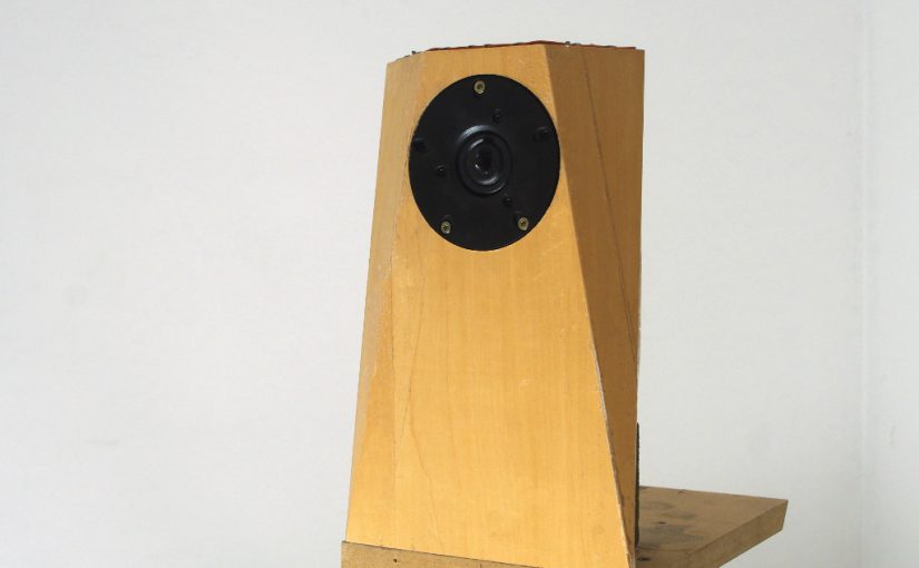
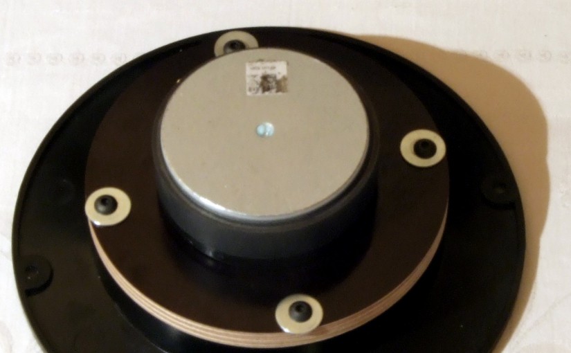
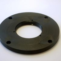
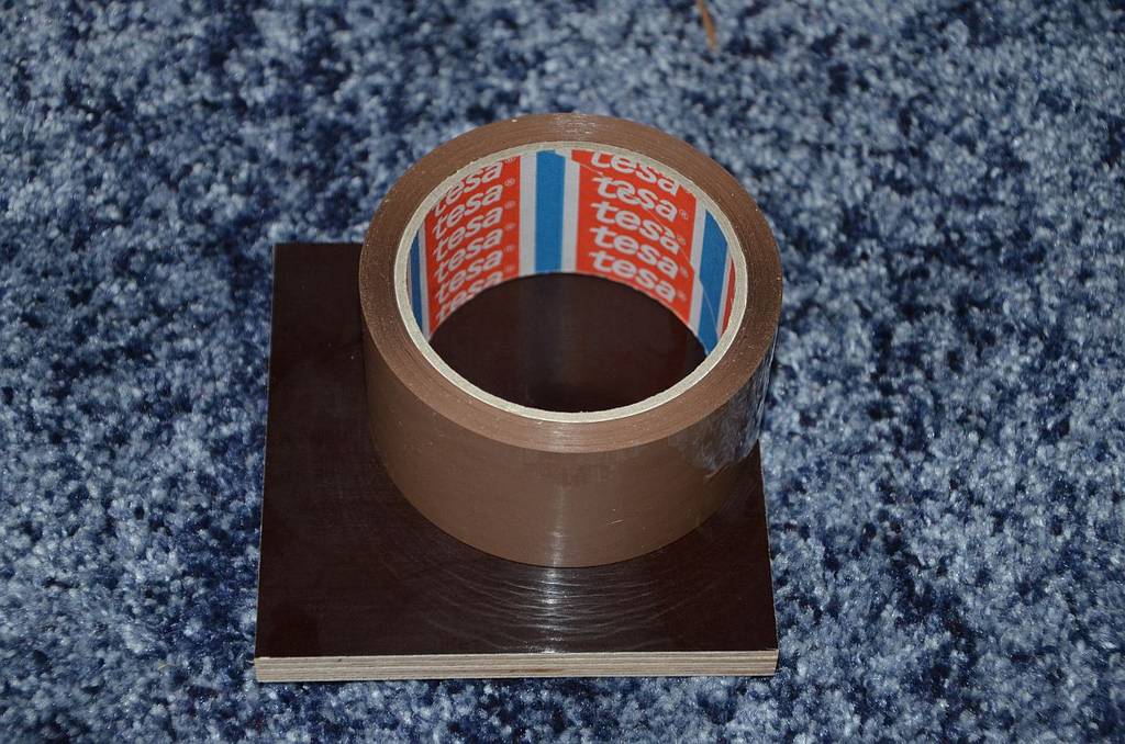
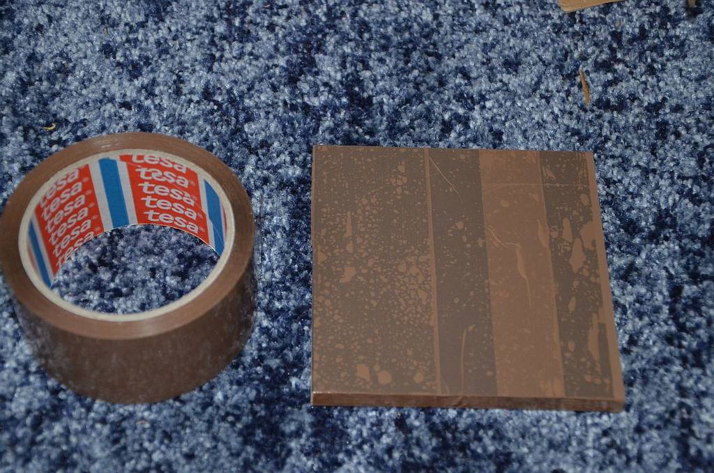
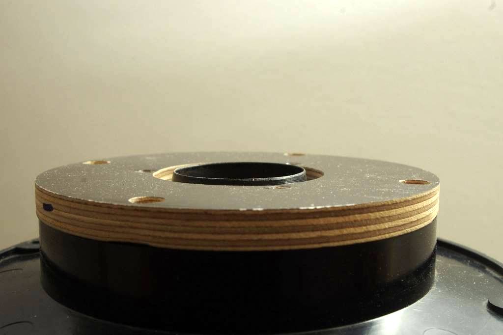
To accomplish this, a baffle with adjustable, beveled chamfers had to be made. After a lot of headache, how to build this, I finally came to the following conclusion:

schraege_fase_variabelA V-groove was milled from behind, slightly less deep than the plate thickness, the whole thing "secured" from the front with adhesive tape and a 2mm thick copper wire stapled from above, which serves as an adjustment mechanism. The "wings" can be set anywhere from 0 ° -55 °.

baffle_xt25_back

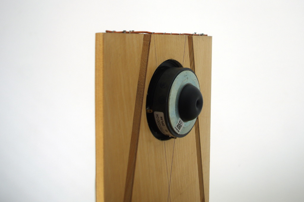
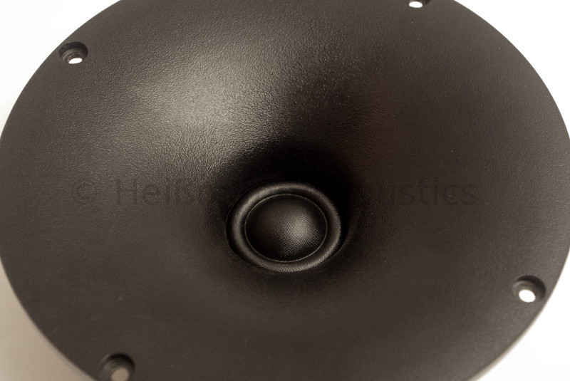
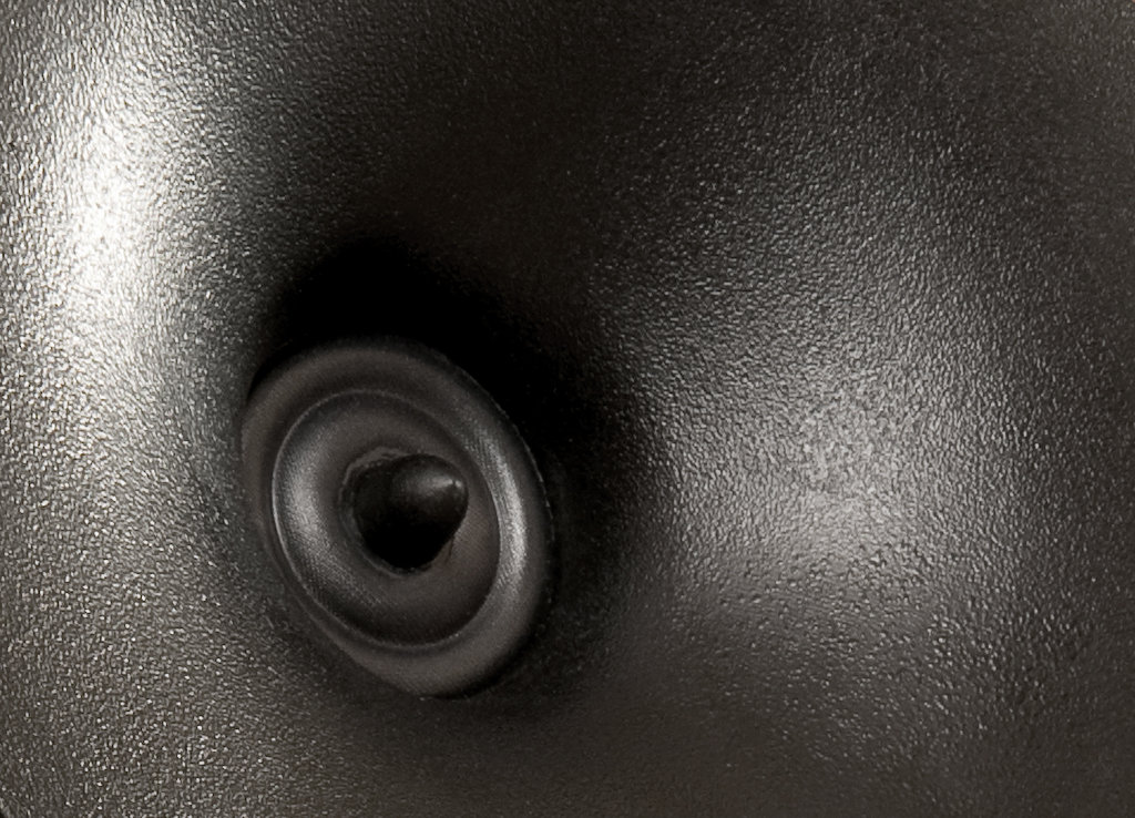
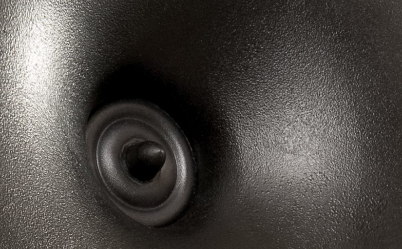
For the tweeter, I chose one that by itself does not show any disturbances in the directional behavior in the area relevant for edge diffraction, which could falsify the results. The choice was much to the one I really appreciate XT25TG-30 / 04.

In 55 ° steps for chamfer angles of o-5 °, the respective radiation behavior of 0-90 ° in 10 ° steps was measured. Altogether 120 measurements.

The initial situation: Bevel angle 0 °

See also "Worst case" scenario

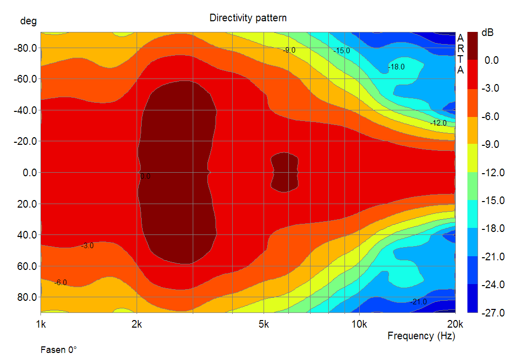
The left picture shows the radiation behavior in a sonogram normalized to 0 °. The right-hand example shows the angles 0, 30 and 60 °.

The sonogram shows that the loudspeaker is considerably too wide around 3kHz and radiates too narrow below that. Axis and angular frequency responses are unbalanced to one another. Where there is a depression on the axis, there is a superelevation at angles. The loudspeaker changes its character with the listening position. A steady and as evenly narrower course as possible would be desirable.

Measurement results

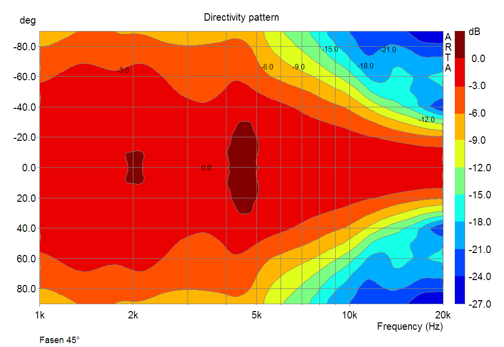
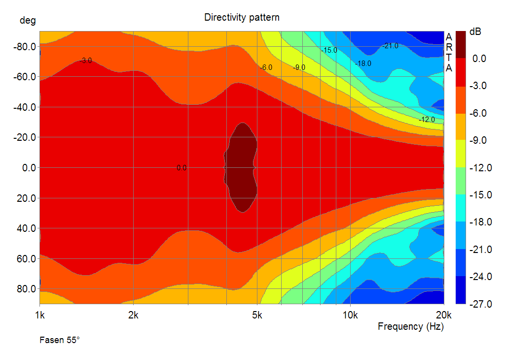
Sonogram for chamfers with a slope of 0-55 ° in 5 ° steps

fasen_deg_var

0,30 and 60 ° for bevel angles of 0-50 ° in 10 ° steps

winkel_fasen_deg_var

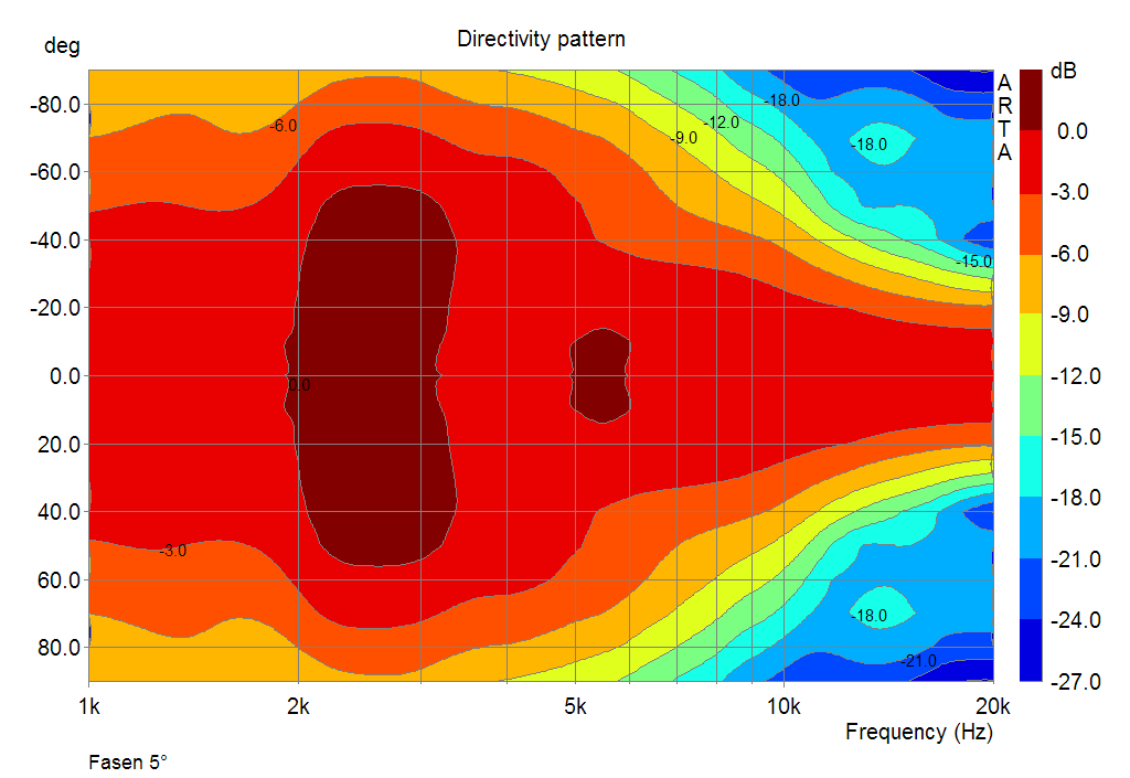
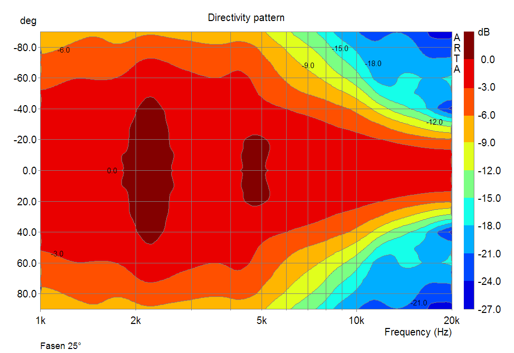
The main disturbance (expansion by 3kHz associated with the constriction below) decreases with a larger bevel angle. Chamfers with a slope of <20 ° do not yet produce satisfactory results.

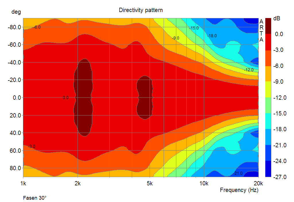
The chamfers themselves form a new edge, which comes to bear with increasing steepness. Recognizable by the arising expansion around 5Khz. This is less pronounced because the tweeter in this area is no longer working as a half-space radiator.

In addition to resolving the "rectangular geometry", this is one of the main tasks of the inclined bevel: bringing the housing edges so close to the tweeter that it no longer "sees" you or only weakly. Shorter distance ⇒ shorter wavelength higher frequency ⇒ more directivity ⇒ less influence of the edge

The “inclined bevel” concept works particularly well when the tweeter is already clearly bundling in the corresponding frequency band and thus it is practically no longer “seen” at all. Of the Seas DXT 27TBCD / GB be mentioned here by way of example. How well this driver works with oblique chamfers is an example DXT-Mon to see.

In summary:

  • Chamfers <20 ° are not sufficiently effective
  • The distance of the chamfers to the place of sound creation must be sufficiently low, otherwise one reaches only one, at least partial, displacement of the problem
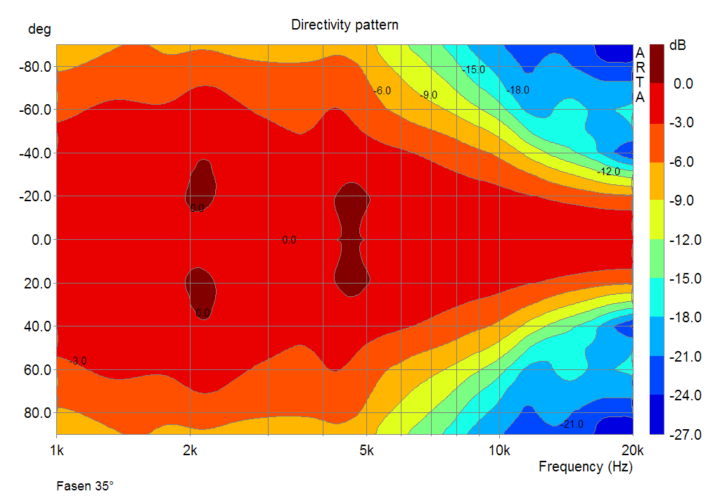
  • Depending on the situation, the chamfers can also zu steep be!

The concept of the bevel chamfers doesn't really work around the problem to get over. But not unconditionally. The slope and position must be chosen carefully and according to the concept. If you were to ask me for a universal recommendation, I would say:

"Make the bevels 25-35 ° steep and position them as close to the tweeter as possible"


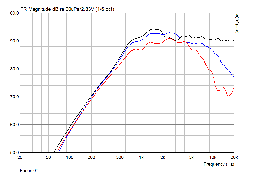
Finally, the measurements in single images, for those who want to take a closer look. The steepness of the chamfer is in the lower left corner of the picture.

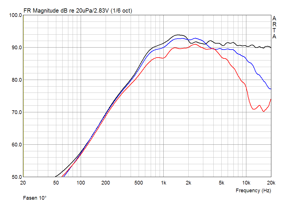
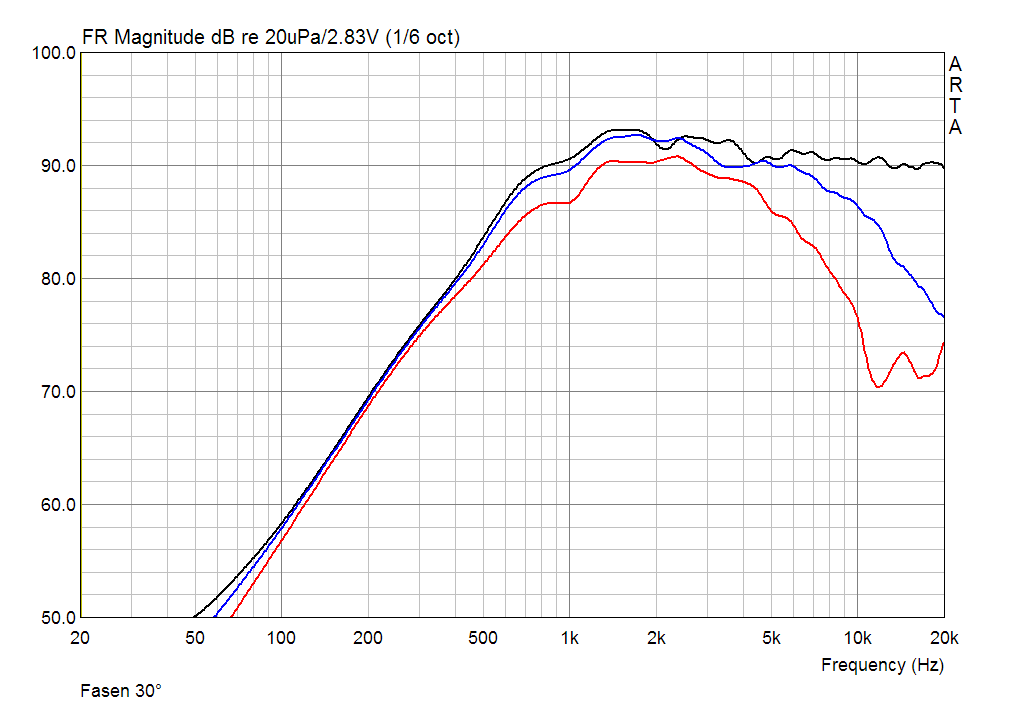
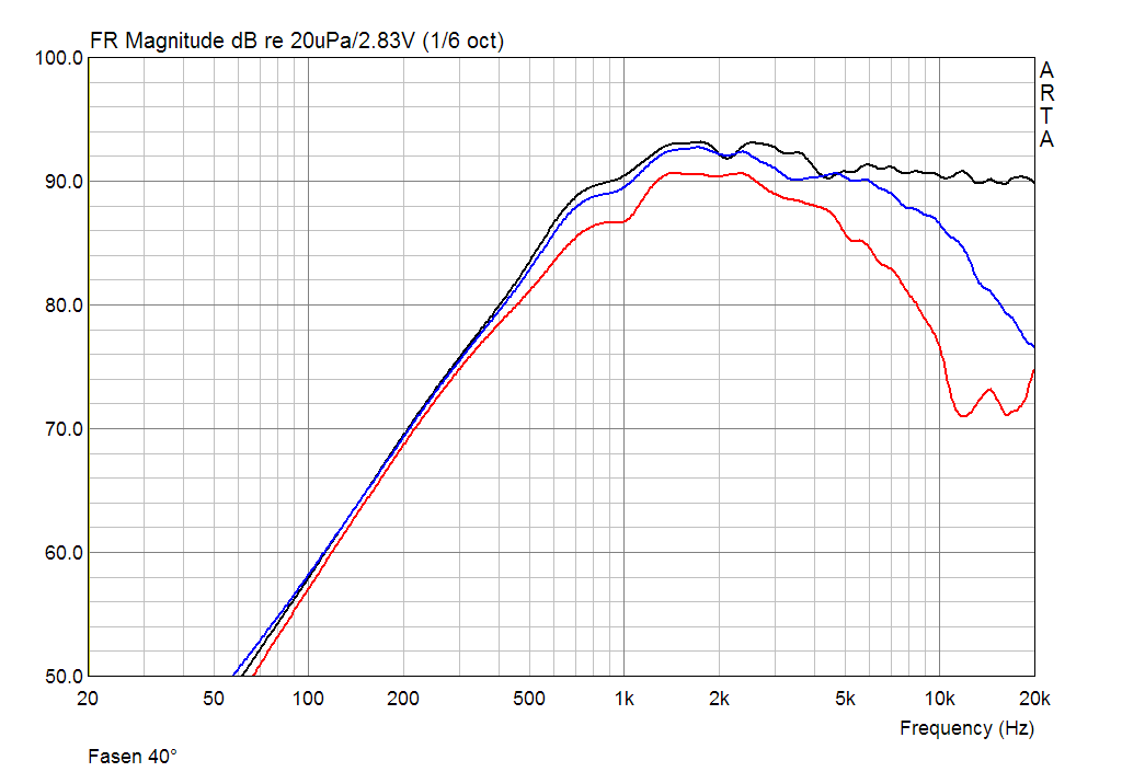
Note: The picture change is also possible with the mouse wheel


CNC adapter plate for various Scan-Speak and Peerless tweeters on WG-300 and PCT-300

There are some tweeters from Scan-Speak and Tymphany, all of which share the same front panel. One or the other of them also measures itself excellently on the P-Audio (PCT-300), or Monacor (WG-300) waveguide.

In order to connect the drivers cleanly with the sound guide, an adapter plate milled in CNC was created after many test series, which allows simple and very precise installation.

The following tweeters are suitable for the conversion

3D printed adapter plate in the shop

Construction of the adapter plate with "home remedies"

With a jigsaw, cordless screwdriver, router and the following step-by-step instructions, building the adapter plate yourself should not cause any problems. It doesn't even have to be measured 🙂 Let's go ...

  • Print out the PDF (included in the respective building folder) using Acrobat Reader (choose the “actual size” option!)
  • Size check: Outer diameter 120mm
  • Glue on a 9mm thick piece of MPX / MDF / screen printing plate (spray glue / glue stick ...)
  • Drilling the holes => upright drilling machine is an advantage!
  • With the circular milling device (each speaker should have one) 3mm deep to appropriate mark milling (D67mm)
  • Use the jigsaw to saw the inner hole and saw off the plate in the last step

From the practice with the "home remedy method" another additional tip from Thorsten (www.felbi.at)

If you glue your artwork directly onto the substrate (eg MPX), you will have the difficulty to get it down again later. For visual reasons, that bothered me and came up with the following idea: Before you glue your artwork on the MPX, just past the MPX with tape. Now the artwork will be cut to the size of the MPX board. Spray glue is then sprayed onto the package tape and allowed to dry for about 5 minutes (Note the spray adhesive is not on the paper spray!). Now the print template can be glued on.

Once all drilling and milling work has been completed, the package strap can easily be pulled down again from the MPX board.


Installation

First, the front panel of the tweeter must be removed. On some models, this is easily fixed with a silicone-like adhesive. In this case, use a large slotted screwdriver to "pry" it up discreetly as shown in the following picture. Work slowly and evenly. The screws on the front panel should of course have been loosened beforehand (TX10).

Dressing the waveguide neck

The adapter plate is placed on the sound guide and the neck is ground flat with circular movements (⇒ dust mask).

Finally, two recordings of the Scan-Speak D2604 / 833000 or 830000 & the Peerless XT25TG30-04 with waveguide

Disclaimer

You do the conversion on your own responsibility! I accept no liability. Possibly. you lose your warranty claims during the conversion.

I made a lot of changes and nothing ever happened. I think the instructions are pretty "foolproof" 🙂

The plans of the adapter plate are the intellectual property of Heissmann-Acoustics.de, Alexander Heißmann. Any transfer requires my express consent.

... you can get a coffee from 1 € 😉

Test Peerless / Tymphany XT25TG-30 / 04 (XT-300 / K4) at the waveguide WG-300 / PCT-300 4 Ω ring emitter with waveguide

Datasheet © www.heissmann-acoustics.de
Measurements in 20x40cm baffle, 10mm rounded, in 70cm distance at 2,83V. Level scaled to 1m.

The Waveguide was milled with a CNC adapter plate  mounted on the tweeter.

XT25TG30_04_WG

XT25TG-30 / 04 Sound pressure at angles

Vifa XT-300 (XT25TG-30 / 04) WG300 Sound pressure at angles

System-related exaggeration in the frequency band of 1-7 kHz. Due to its symmetry, this can be easily equalized with the crossover. It is the purpose of a sound guide to act as an acoustic amplifier. The Vifa XT-300 (XT25TG-30/04) is an excellent match for the waveguide. Extremely even bundling without any disturbances worth mentioning. Due to the large dome (30mm voice coil), a slightly stronger directivity from 8kHz. Recommendation: plan a slight increase> 8kHz in the high frequency on axis.

XT25TG-30 / 04 Sound pressure standardized at angles to 0 °

Vifa XT-300 (XT25TG-30 / 04) WG300 Sound pressure normalized at angles

Vifa XT-300 (XT25TG-30 / 04) WG300 Sound pressure normalized at angles

Here, the frequency response was linearized on axis. The 2. Picture (sonogram) clearly shows the excellent uniform straightening behavior of the combination of XT-300 and the waveguide.

XT25TG-30 / 04 decay behavior

Vifa XT-300 at Waveguide WG-300 decay behavior

Minimal delayed decay by 2kHz. Otherwise perfectly.

XT25TG-30 / 04 harmonic distortions

Vifa XT-300 at the waveguide WG-300 harmonic distortion

As expected, the distortion decreases compared to the variant without waveguide. The XT-300 already showed very good distortion even without waveguide, but with a significant increase of K2 under 3kHz. With Waveguide the effect is also present but attenuated by about 5dB. In sum, very low distortion. Even with 100dB, everything from 2kHz remains below 1%. K3 moves at the measurable limit.

Rating


Frequency response / directional behavior:4.5 5 out of stars
Range:5 5 out of stars
Power handling:5 5 out of stars
Constance / Without Rating /:0 5 out of stars
Haptics:4 5 out of stars
Price-performance:5 5 out of stars

Conclusion


The Peerless XT25TG-30/04 and the Waveguide WG-300 are a very attractive combination for extremely level-stable installations, for example in the home theater. Can be used from 1,5 kHz. I think I'll test it out in Cinetor.